Step 1: Preparation
Clean all parts thoroughly. Bearings in gasoline, other parts in kerosene. Check every component against specifications. Only perfect parts proceed.
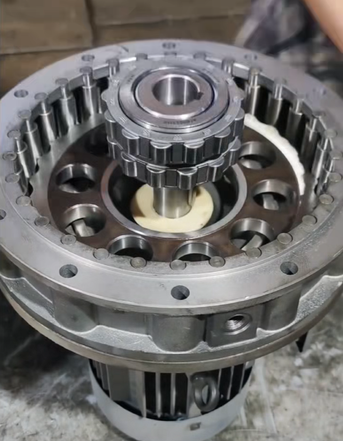
Step 2: Install Bearings & Gears
Heat bearings to 100°C in oil. Slide onto shafts, tap gently with copper rod until seated against shoulder. 0.05mm feeler gauge must not pass through. Install gears—large first, then small. Heat and press into position.
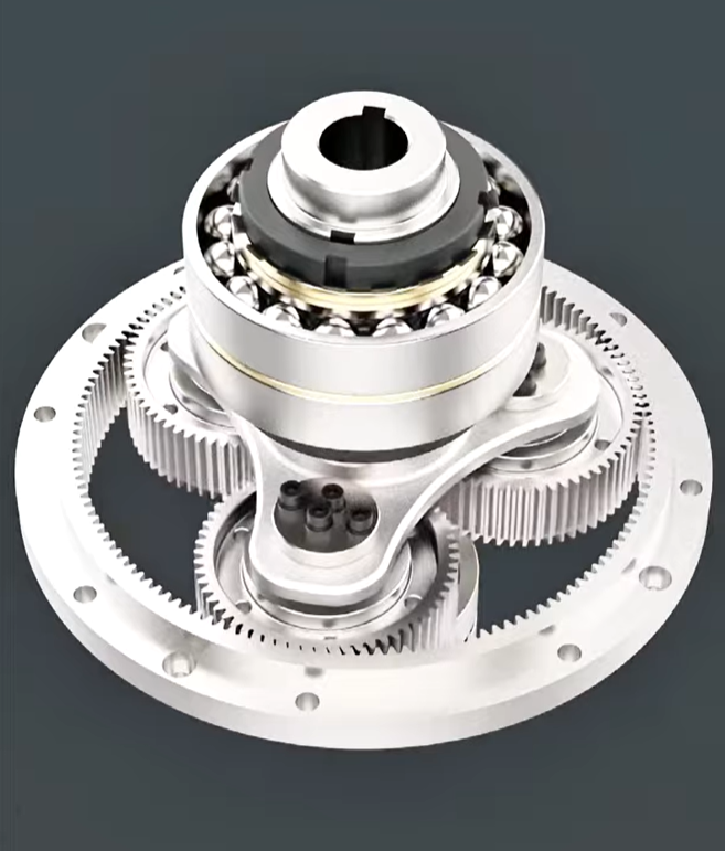
Step 3: Assemble Shafts & Housing
Level housing to within 0.1mm/m. Insert shafts carefully. Stack gear cartridges for multi-stage units.
Step 4: Adjust Clearances
Check backlash with lead wire method—must meet specs. Test contact pattern with marking compound. Requirements: 40% along tooth height, 50% along tooth length.
Step 5: Close Housing
Apply sealant to split surfaces—no gaskets. Insert taper pins, tighten bolts from center outward in multiple passes to specified torque.
Step 6: Test Run
Run no-load for 1-2 hours forward and reverse. Then load test to full capacity. Monitor temperatures: oil rise ≤35°C, bearing rise ≤40°C, ≤15°C. Check for noise and leaks.
Step 7: Finalize
Add correct oil to specified level. Install cover, open vent cap. Coat exposed shafts with rust preventive. Final QC check—ready for shipment.
Quick Checklist
- Bearings seated: 0.05mm gauge no-go
- Backlash: meets specs
- Contact: height ≥40%, length ≥50%
- Bolt torque: correct
- Temperature rise: ≤40°C
- No leaks, no noise
Golden Rules
| Do | Don’t |
|---|---|
| Heat bearings to 100°C | Hammer directly on parts |
| Use copper rod for tapping | Heat bearings above 120°C |
| Tighten bolts symmetrically | Add gaskets between split surfaces |
| Open vent cap before running | Operate with vent closed |
FODABEARING — Precision drive solutions.